The main difference between the finite element analysis of parts and assemblies is the component contact definition section. In this study, we are going to review the contact types when analysing assemblies.
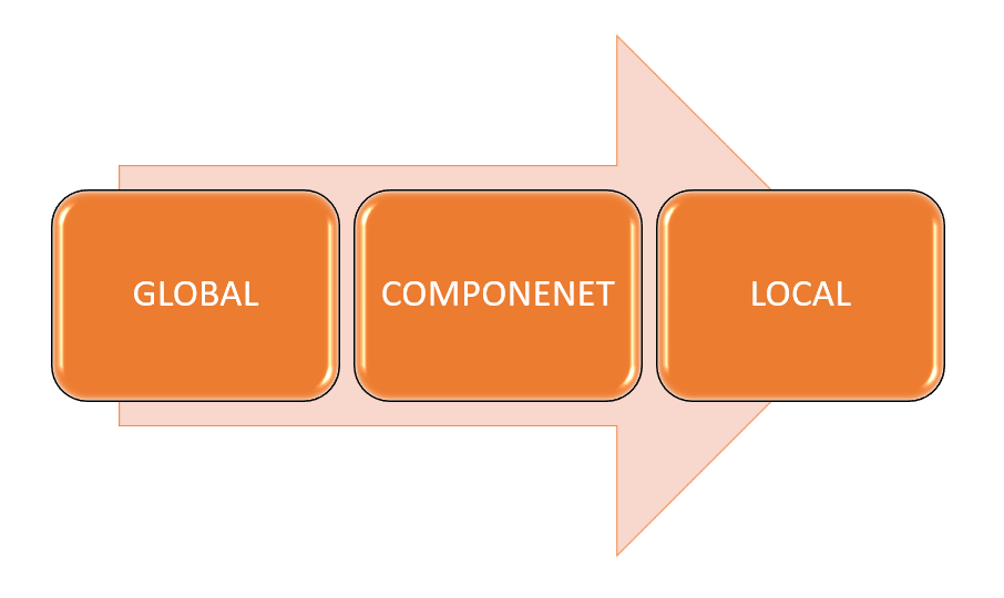
There are three levels of contact between parts: local, component and global. The level of priority in contact hierarchy from low to high is: GLOBAL, COMPONENT and LOCAL. It means that if thee is a conflict between the locally defined contact and the global contact type, software applies local contact and ignores the global contact type, figure (1) demonstrates the hierarchy.
While the global contact could be cancelled by the local contacts; but, it has direct effect on model stability during analysis. It is recommended to don’t change the global contact and use local contacts to characterise the contact between parts.

Global Component Contact Types
By global component contact type, we can define how all of the parts in the assembly interact with each other; then by local contact definition we could adjust the contact type between parts.
Are they bonded (welded) together, if they could slide on or they could penetrate into each other. To achieve this definition there are three contact options available: Bonded, Allow Penetration and No Penetration, figure (2).

Bonded
By default this is the selected global contact type. This contact type means that all touching faces (or faces with a specific gap between them [when the “Non-touching faces” option is selected]) are bonded together and remain touching (or the gap between them stays at it was at the beginning of the analysis) and the assembly reacts like a part.
No Penetration
This option allows parts not only impose force to each other; but also, to separate from each other; but, they couldn’t penetrate into each other. For this contact type you could define coefficient of friction.
In SolidWorks 2021, this term has a new name, in SolidWorks 2021 it is renamed to “Contact”.
Allow Penetration
By this selection, parts almost ignore each other and could penetrate into each other. There is a rare application for this type; unless, for specific analysis types like frequency or buckling.
Local Contact Types
To access to the local contact, right click on the connections and select contact set, figure (3) [left]. You have five different options for local contact type, figure (3) [right]: No Penetration, Bonded, Allow Penetration, Shrink Fit and Virtual Wall.
Bonded and allow penetration are the same as what described in global contact types.
Before describing Shrink Fit and Virtual Wall, lets explain what all of them have in common: the blue and pink boxes under the type. By this boxes you could select the surfaces that are going to be affected by the type of contact that you select. The blue box is called Set 1 or Origin and the pink box is Set 2 or target.
It is suggested that the Set 2 is better to be flatter and larger than Set 1 and Set 1 better to have smaller mesh size than the Set2.
![How to access local contact set [left]: Right Click on Connection on the simulation tree, available contact types for local contacts [right]: No penetration, Bonded, Allow Penetration, Shrink Fit, Virtual Wall](https://esolidesign.com/wp-content/uploads/2021/08/image-6.png)
No Penetration
How this contact behaves is the same as the global contact; but, when you select this type in local contact type, you could set couple of parameters. The parameters are:
Friction: You can define coefficient of friction between two parts in here,
Due to increase of computational time, it is better not to use option; unless, you are sure about the amount of friction value or you want to stabilize your model.
Gap (Clearance): By this option you could put limit on how far two parts could get close to each other.
Self-Contact
This option detects the part areas where they can come touch with each other during the analysis; then, a no penetration contact is applied to a face that touches itself.
Advanced Section
When you No Penetration and Shrink Fit types, on the advance section you have three (one) choices:
Node to Node:
For this option both surfaces should be in touch (inherently means no initial gap) and there shouldn’t be change in the contact region or a very little sliding. This option provides the fastest solution for this contact type without accurate contact pressure results. For this option nodes on either of contacting surfaces don’t move in relative to each other. The global contact should be bonded and mesh should be compatible. Also, this is not a good selection for Large Displacement Analysis.
Node to Surface:
Unlike “Node to Node” there could be a gap between the surfaces, the mesh could be incompatible and it could be used for Large Displacement Analysis. This is the default selection and is especially useful when the contact stress is out of our interest. This option takes more time compared to “Node to Node” option.
It is a good selection when an edge could contact a surface.
Surface to Surface:
Like “Node to Surface” there is no limit on the gap between surfaces and the mesh could be incompatible. As you might expect, this method leads to the most accurate results for contact stress between these three options. This option is suitable for Large Displacement Analysis and for when we expect a face to face contact is possible.
Improve Accuracy for Contacting Surfaces
If contact stress is the main purpose of the analysis, you could increase the accuracy of results in cost of more analysis time. To do that, follow these steps:
- Right click on the analysis name and select properties, figure (4) [left],
- On Options tab select “Improve accuracy for …”, figure (4) [right].

Shrink Fit
A classic example of shrink fit is insertion of a shaft into a hole where the shaft diameter is bigger than the hole diameter. This contact type is the only type that not only allows; but also, requires a limited volume of interference between the parts.
Shrink fit only has “Surface to Surface” option in Advance Section. The definition is the same as “Surface to Surface” condition in No Penetration contact type.
Virtual Wall
This contact type is especially useful when you are going to include in your model effect of vertical/ horizontal support (like ground) on your model. Instead of modelling/ meshing a part you can use this feature in your analysis.
This contact type is similar to no penetration contact. For this contact type you need a plane. The wall could be either rigid or flexible.
Unlike other contact types, when you create this contact type, it appears in Fixtures section of simulation tree rather than Contac Sets.
Contact Type Symbol
Each of these contact types has its own symbol which could be seen in figure (5).

What is Next:
On the next whitepaper, we will dig in more about assemblies.


