Reading Time: 4min.
In this paper, Finite Element Analysis, its applications and its inherent errors are discussed and the available mesh types are reviewed.
The main focus of this paper is on the SolidWorks Simulation.
What is Finite Element Analysis?
Finite Element Analysis or FEA, is a numerical method for solving partial differential equations (PDEs) for engineering and mathematical systems. FEA was developed by engineers to find solutions for mechanical and structural problems in the fields of aerospace and civil engineering.
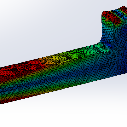
To solve PDEs, the under study system (domain) is discretized into smaller parts or Elements, each element is made by joining a number of Nodes. FEA method numerically estimates the solution in the nodes and interpolates them to calculate it inside the element.
The backbone of calculations in FEA is minimizing the total energy of the domain, it means that if a domain has several possible solutions, the answer with minimum total energy is accepted.
This method has been well developed and used. Nowadays it is being used to solve different problems like mechanical, structural, thermomechanical, biomechanical, fluid mechanics, piezoelectrics and more.
An important note, FEA is a tool and like all other tools the outcome highly depends on the skills of the user.
What are errors in FEA?
The user of FEA should be aware of three types of errors in this tool while he is doing FE analysis, these are:
- Modelling Errors,
- Discretization Errors,
- Solution Errors.
Modelling Errors:
Modelling errors or simplification or idealization errors, as the name suggests happen during describing the model geometry and conditions (supports, loads, contacts, element types).
Finite Element Software tries to solve PDEs to satisfy the boundary conditions. Wrong definition of boundary conditions would lead to different solutions.
Errors in this group could be result of either of these cases:
- Incorrect geometric definition (wrong beam element dimension/ orientation, wrong support type/ location, inaccurate load (location/ type/ magnitude) and unit mixed-up,
- Inaccurate material description,
- Inaccurate/ insufficient contacts between parts in assemblies,
- Wrong analysis type.
Discretization Error:
This error happens when the domain is transferring from the physical word into the mathematical environment by dividing the physical case into small elements (meshing).
This error stems from different mistakes:
- Inadequate mesh density,
- Incorrect mesh type selection,
- Wrong mesh order
In SolidWorks Simulation there are two element orders:
- first order elements (Draft Quality),
- second order elements (High Quality).
Solution Error:
This error occurs during integrating the solution on the PDE domain. this error is due to:
- Accumulation of roundings during calculations,
- Integration and Matrix conditioning errors (beyond the scope of this paper).
Element Types in SolidWorks Simulation
There are three main types of elements (based on their shape and the space they fill) in the SolidWorks Simulation:
- Solid Tetrahedral Element,
- Shell Triangular Element,
- Beam Element.
Solid Tetrahedral Element:
This type is a 3 dimensional (3D) element that is made of four nodes and is the best candidate for solid meshing. The ideal tetrahedral element has a 60 degree angle at each node (on the other words, all edges have the same length).
The main drawback for this element type is the resource requirements for completing a FEA, as a rule of thumb, the running time of an analysis is a function of number of elements power two.
So, to save available resources and find the solution quicker especially in the early design stages (concept design) it is better to idealize the model with simpler element types (if possible).
Shell Triangular Elements
This type is a 2D element and is made of three nodes and is the best and the most economical option for thin elements. Shell elements only tolerate membrane (in-plane) and bending loads and bending stress is linear through the thickness.
The application of this element is for sheet metal parts, pressure vessels and hydrostatic gate plates.
As a general rule, to obtain accurate results for shell elements, the ratio of the smallest length to the thickness should be more than 15.
Beam Elements
This is the simplest element type (1D) and is made of 2 nodes; consequently, the FEA of this element type is the fastest. This element type is divided into to subgroups:
- Beam Elements
- Truss Elements
The criteria to select the right subgroup is the ratio between the span to the depth of part (figure 1). If this ratio is more than 10, the beam element is the correct choice.
Figure (1)- Span and Depth of a Beam Element
Differences between these two subgroups are presented in the following table.
| Item | Beam Element | Truss Element |
| Required properties for element definition | Cross section Area, Moment of Inertia and Torsional Constant | Cross Section Area only |
| Loads on the End Nodes | Normal/ Shear load, Moment and Torsion | Load only at the End Points (Joints) |
| End Node Degree of Freedom (DOF) | 6 | 3 |
| Number of Elements in the length of Beam | As required | 1 |
| Ability to Carry load along the member | Yes | No |
| Joint Control Between Elements | Yes | No (pin joint at each end) |
What is Next:
In the next paper, the element type orders, mesh quality, difference between compatible and incompatible mesh, Adaptive meshing techniques (h- adaptive and p-adaptive) will be reviewed.


