In this article we review the steps that should be followed during finite element analysis. To achieve meaningful results, all these steps should be understood well.
Problem Description
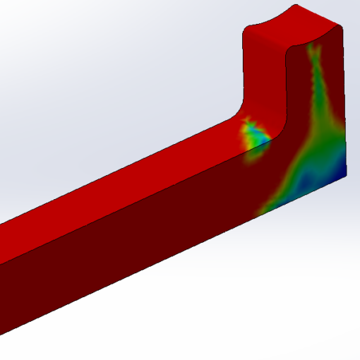
The problem here is FEA of a notched rectangular bar, figure (1) under tension load (F=10kN); then, compare the FEA results with academic findings.

Finite Element Analysis Steps
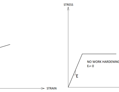
The flow chart (1) represents the steps that should be taken for carrying out a FEA.

It should be noted that after evaluation of analysis, most likely, it is needed to review the fixtures/ contacts and mesh density; then, run the analysis couple of more time to get more accurate results.
FEA with SolidWorks Simulation
Before starting the analysis, it should be noted that for this article SolidWorks Simulation 2018 was used, so you might see some differences if you are using different version of SolidWorks.
***** To keep this article concise, we are not going to list all of the possible ways of doing a task. Moreover, figure numbering will be restarted in each section.
1- Create a Study,
Open SolidWorks, Select Sketch command, Select the front plane and Draw the sketch in figure (1-1); then extrude it by 10mm.

From the command manager, click on Simulation tab, figure (1-2).

If you cannot see this tab, right click on one of the existing tabs, and select simulations, figure (1-3).

From the drop-down icon of “new study” select “New Study”, figure (1-4); next, rename the analysis to “Stress Concentration” and select “Static”, figure (1-5).


After study creation, SolidWorks Simulation automatically create a study folder figure (1-7), named “Stress Concentration” here.

2- Apply Material
Right click on part name (here, part1) and select Apply/ Edit Material…, figure (2-1); then, select “Plain Carbon Steel”; next, click on Apply bottom figure (2-2).


Just a note, red properties in the material properties table (like Elastic Modulus in here), means that they are mandatory properties for that simulation type and should not be empty.
After assigning material, a green tick will be added to the part icon, figure (2-3).

3- Apply Fixture
Before starting this section, let us quickly review the available standard fixtures in SolidWorks Simulation Table (3-1), advanced fixtures will be reviewed in the future lessens.

Right click on the Fixtures and select “Fixed Geometry”; then select either of side faces, figure (3-1), click OK.

4- Define the Load
Before applying load to the part, we review the Standard External Forces in table (4-1). Advanced External Forces will be reviewed in more relevant lessens.

To apply load, right click on External Loads and select Force, select the opposite face to the fixture face (in step 3), select Normal, in the Units select SI; next, type 10000 in force value, tick the Reverse direction box if required, and click OK, figure (4-2).

5- Mesh the Model
Right click on the Mesh and select Create Mesh… (5-1).

Keep Mesh Density as it is, for automesher algorithm, select Curvature-base mesh, keep “maximum element size”, “minimum element size” and “element size growth ratio” as they are. Keep Draft Quality Mesh, unchecked, figure (5-2).

The differences between automesher types are presented in table (5-1).

Note: as advised in the beginning of this paper, the version of SW is 2018, in the last version of SW (SW21) the algorithm for “Blended Curvature” automesher well developed and is the most recommended automesher for this version (SW21).
What is Next:
In the next paper, we will run this analysis, review and discuss the results.


